This tutorial will guide you step by step in the creation of a realistic Planet Earth scene, focusing on materials and shaders in Away3D 4.x.
Contents:
Introduction
Away3D is a powerful 3D engine that abstracts us from the powerful, yet low level Stage3D API. In just a few lines of code, we can accomplish advanced scenes and let the engine take care of the rest. Such is the case for advanced material usage. In this tutorial we will take a quick tour along Away3D’s material system in trying to emulate a scene depicting our beautiful planet Earth, floating ominously in deep space. We will start from simple geometries and materials, and little by little get more and more involved into the engine’s powerful material system. So let’s get started, enjoy the ride!
Setting Up the Scene
First things first, lets set up the geometries of the scene. We will use spheres to create the Earth and the Moon, group them appropriately in order to be able to simulate axis and orbit rotations, and texture them with basic materials. Listing 1 shows our basic set up:
Listing 1 ( click image to launch ). Basic Earth scene with grouped transforms and non-lit texture materials. Full source code.
For each celestial body, we’ve reproduced the same sequence of steps. We’ve created a texture, a geometry, wrapped them in a mesh object, added it to a containerand added the container to the scene. Lets quickly review each of these steps.
Materials:
We are embedding jpg images and using Away3D’s Cast utility class to create BitmapTexture objects. Note that these are not the regular Flash BitmapData objects but special GPU image objects that Away3D will eventually upload to the GPU via the Stage3D API. These are then used within a TextureMaterial, which is the engine’s main player in any material that makes use of textures for shading. In this case, we’ve barely made use of this powerful material, but we will take much more advantage of it, as we will see shortly.
var moonSurfaceTexture:BitmapTexture = Cast.bitmapTexture( MoonSurfaceDiffuse );
var moonSurfaceMaterial:TextureMaterial = new TextureMaterial( moonSurfaceTexture );
Geometries:
The celestial bodies are represented by SphereGeometry objects. A geometry object is mainly a buffer holder, keeping track of a potentially large number of triangles. Such can represent a plane, a sphere as in this case, a torus, or even much more realistic and complex objects such as a detailed car or avatar shape. Away3D offers a basic set of primitive geometries and in this case, we are using spheres with a significant level of detail, that is, with a pretty high poly count or segmentation, to make sure we see perfectly rounded bodies.
var moonSurfaceGeometry:SphereGeometry = new SphereGeometry( 50, 100, 50 );
Meshes:
Geometries combined with materials conform mesh objects, which gather the necessary functionality for actual rendering. The geometry determines the object’s shape, and the material determines the object’s shader, or how it will be drawn to screen. Meshes also wrap other objects, such as transforms. These are another essential part of the 3D rendering pipeline and allow us to position, scale and rotate our objects in the scene. Notice how we altered the x coordinate of the moon body.
var moonSurfaceMesh:Mesh = new Mesh( moonSurfaceGeometry, moonSurfaceMaterial );
Containers:
Another object that owns transforms is ObjectContainer3D. These can also contain children. In our example, we are placing the objects within containers so that it is easy to perform groupings and transformations on them. For example, by displacing the moon’s position within its container, we can simulate its orbital motion by simply rotating its parent container. These are the objects we finally add to the scene.
Our scene still looks pretty bare and there are several aspects we could focus on to make it look better. We could work on the object’s materials, and we will, but something we could at look at first is adding more elements to our scene in order to populate it with a bit of eye-candy. We will add the Sun, some stars, and deep space graphics to our scene. Lets look at the result first, and then analyze what we’ve done.
Listing 2. The basic scene with Sprite3D’s to represent the Sun and stars and a SkyBox to represent deep space. Full source code.
We’ve compacted the code from the last listing. As we advance in this tutorial, our code is going to get more and more involved, so we will want to have previously studied elements in the source out of our current main focus. Our listing has three new methods, one that creates the sun, another that creates a starfield and another one that creates our deep space graphics using a skybox.
Sprite3D
The sun and the stars use Sprite3D instead of Mesh. These are objects that don’t really have a geometry, but still own a material, a transform, etc. Their geometry is actually a plane that always looks at the camera. These are commonly known as billboards in the 3D world, and are ideal to represent potentially numerous far away objects or particles. They can be ‘faked’ with an image attached to a plane, and that is exactly what we are doing here. Sprite3D’s use much less triangles than Meshes and are hence cheaper.
Notice the new method blackToTransparent(). This is simply a utility method that changes the black background of the images we are using on the billboards to transparent. The way we do this is by creating a new BitmapData object and copying anything on the image’s red channel ( anything that is not black ) to the alpha channel. We could have used any of the other channels since the images are pretty much black and white, but the red channel will do. Once we have such transparent images, setting the material’s alphaBlending property to true, will let the rendering pipeline know that this object’s texture is to be alpha-blended with whatever objects are behind it.
var bitmapData:BitmapData = blackToTransparent( Cast.bitmapData( StarTexture ) );
var starMaterial:TextureMaterial = new TextureMaterial( new BitmapTexture( bitmapData ) );
starMaterial.alphaBlending = true;
The star field is layed out using a for loop that creates each billboard, spits out random spherical coordinates, calculates its cartesian coordinates equivalent and assigns it to the position of each star. We used spherical coordinates here because they tend to be easier for laying out things in a spherical distribution. You can read more about this system and its uses here.
SkyBox
Another commonly used trick we’ve used here is the skybox. This is simply an infinitely large cube with images attached to its inner faces, ideal for simulating environmental elements that are sufficiently far away do not require parallax or perspective effects. They are so far away, that moving around won’t actually make them look very different. For this, we embed 6 images, one for each face of the cube and wrap them around a BitmapCubeTexture, which is another type of GPU texture for the Stage3D API, and then wrap this texture in turn in the SkyBox object itself. This is a simple resource, cheap and with excellent visual contributions.
// Cube texture.
var cubeTexture:BitmapCubeTexture = new BitmapCubeTexture(   Cast.bitmapData( PosX ), Cast.bitmapData( NegX ),   Cast.bitmapData( PosY ), Cast.bitmapData( NegY ),   Cast.bitmapData( PosZ ), Cast.bitmapData( NegZ ) );
// Skybox geometry.
var skyBox:SkyBox = new SkyBox( cubeTexture );
_view.scene.addChild( skyBox );
Great. We now have a rich scene populated with many objects. Let’s see what we can do next.
Lights
Now that we have sufficient objects in our scene to make it a bit richer, its time to make or celestial bodies look a little more realistic. A fundamental aspect of 3D graphics that that we have ignored so far is lighting. Light sources and light enabled materials shade objects depending on the configuration of the light sources and materials. This provides a powerful enhancement to our scene. Let’s see how it looks like when applied.
We haven’t changed much in this listing, just added a point light, adjusted some settings on it and on the materials, and associated the lights with the material’s lightPicker property. More on this soon. There are different types of lights in Away3D, PointLight being one of them. This represents a light source that emanates light from a point in space, in all directions. There are other types of lights like DirectionalLight for example, which emanates light from no particular point in a single direction. Each type of light produces a different effect. In our case, we’ve used a point light and placed it at the same position of our sun sprite. We’ve also placed this light in an array and assigned it to our listing’s StaticLightPicker. A lightPicker is simply an object used to group and collect lights in a scene. Consecutively, this light picker is assigned to each of the materials that we want illuminated. In this case we’ve applied it to texture materials but the same thing could be done to other types of materials such as color materials. Under the hood, the result is that Away3D produces a phong shader model to illuminate the affected objects.
Phong Shading
Shading via Stage3D uses a rather complicated shading language called AGAL. It looks almost like assembler and is quite hard to code. It allows us to produce shader programs which can be uploaded to the GPU and, and together with geometries, textures, transforms, etc, define how things are drawn to screen. Fortunately, Away3D wraps all these complexities into an intuitive material system where we can control shading models by simply manipulating parameters and properties. Here, we’ve touched on the light source’s ambient, diffuse and specular values and the materials’ gloss values. The ambient property of the light illuminates objects from no specific origin or direction, simulating a scene’s random reflectance with no specifically directed shading. In this case, we’ve set it to 1 so that the dark side of our celestial bodies are not completely in darkness. The diffuse property affects the amount in which incident light on the geometry’s normals illuminates it. We’ve set it to 2 to exaggerate the difference between the lit areas and the ones in darkness. The specular property of the light affects how much the reflecting highlight (depending on the incident direction of the light), the surface normals and the view angle light the surface. Finally, the gloss property of the material determines how spread out the specular highlight is. Try different values for each, you’ll get a better glimpse of what each does if you do so. Or if you want to dwell deeper into the fantastic world of shading, this is a good place to start. It’s GLSL instead of AGAL, but the concepts are what matter.
One thing to note and that is sometimes confusing is that materials, as lights, share some of the ambient, diffuse and specular properties. These values get combined in the shader so you can have, for instance, different ambient illumination on a set of objects affected by the same light source.
Additional Maps
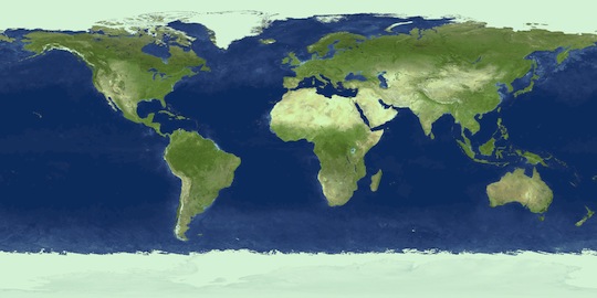
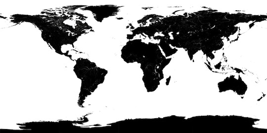
Lighting did improve the look of our celestial bodies didn’t it? There is still a lot more we can do to enhance them though. TextureMaterial accepts more than one texture or map. In fact, we will be applying 3 more maps on it now; a normal map, a specular map and an ambient map. Here they are, including the map we already used:
Figure 1. Multiple maps used for shading of the globe. In order, diffuse map, normal map, specular map and ambient map.
TextureMaterial is able to use these maps for more advanced use of illumination. Lets start by the specular map, which is the easiest to understand. This map simply acts as a sort of mask for the specular highlight of the material. Wherever the map is white, the specular highlight is allowed to exist, wherever it is black, it is not. Values in between attenuate the highlight. The ambient map is used as a sort of diffuse map wherever no light reaches the geometry. In our case, it will ‘paint’ the dark side of the Earth since it doesn’t receive any lighting from the sun. The normal map is a little more involved and produces the illusion of having a higher poly count on our model using a technique known as normal mapping. A SphereGeometry has normals at each vertex and the shader uses each of these normals for determining the diffuse and specular components of the globe’s illumination. In fact, the shader interpolates these normals for every ‘pixel’ or fragment within each triangle producing a very large number of normals, all pointing away from the center of the sphere. This map encodes how much these normals deviate from their original directions by representing the deviations in x, y and z in the red, green and blue color components. This gives a lot more illumination information to the globe when lit, while not actually adding any triangles whatsoever. Lets see the result of using all these maps together. Notice how specular highlights occur only in the oceanic areas, how the dark side of the planet shows city night lights and how normal mapping appears to shade the terrain, while not actually adding terrain elevations near the edges of the sphere.
The following listing implements all these maps.
Listing 4. Usage of additional maps for shading of the Earth. Full source code.
As you can see, these rather advanced shading topics are absurdly easy to implement on Away3D. The most significant change in the listing is the addition of the following lines, which simply assign the mentioned maps into the Earth’s TextureMaterial:
Additionally, notice that we have tweaked illumination values of each of the bodies independently, in order to achieve the desired aspect of each one.
Fresnel Specular Method
To be honest, our specular highlights on the celestial bodies still don’t look very realistic. They do make things look more interesting, but they would truly be more appropriate for billiard balls than for celestial bodies. Planets aren’t that shiny. Also notice an undesired specular highlight trail off when looking at the bodies from behind. Lets change the way our TextureMaterial deals with specular highlights. In fact, lets tell it to use a completely different specularMethod. Away3D materials allow you to composite a material using methods. For instance, you can change the ambient, diffuse and specular methods of a TextureMaterial. You can think of methods as being interchangeable chunks of shader code which the engine combines to produce a completed shader program. This gives you an amazing range of shading possibilities with a very simple ease of use.
To improve our highlights, we will use a FresnelSpecularMethod. This is an illumination technique that sounds very complicated, but is actually very simple. The concept is as follows: If the viewer is looking down on the surface producing the specular highlights, they’re weak. If instead he is aligned with the surface and looking at it edge on, the highlights are strong. Imagine yourself looking at a pool of water on a sunny day. If you stand by the pool and look straight down, you will see little light reflected on the surface and you will be able to see the bottom of the pool. If instead you’re in the pool and looking at the water with the sun in the background, you will see little of the pool’s bottom and see much more light directly reflected from the sun on the surface of the water. Implementing this on our example produces subtle results, but eliminates the desired effects we discussed before, producing a more realistic simulation.
Listing 5. Fresnel specular method implemented on the surface of the Earth and the Moon. Full source code.
Once again, the implementation in code is very simple. We simply initialize FresnelSpecularMethod objects and assign them to the materials of the Earth and the Moon. Magic!
var earthFresnelSpecularMethod:FresnelSpecularMethod = new FresnelSpecularMethod( true );
earthFresnelSpecularMethod.fresnelPower = 1;
earthFresnelSpecularMethod.normalReflectance = 0.1;
earthFresnelSpecularMethod.shadingModel = SpecularShadingModel.PHONG;
//...
earthMaterial.specularMethod = earthFresnelSpecularMethod;
Adding Clouds
The planet Earth contains a rich atmosphere and our simulation would become so much richer if we considered it. We will do this first by adding a slightly bigger transparent sphere to the earth container with a texture of clouds. The implementation is naive in a sort of way, but impressively effective:
Listing 6. Representing clouds using a slightly larger, transparent sphere. Full source code.
You may be asking yourself why didn’t we merge the earth surface and sky diffuse maps, or even layer the materials in some way? This would definitely save us a lot of triangles since using a new sphere certainly adds a lot of them. Well, we can afford them in this scenario, plus, if we merged the maps together, the additional maps we added to the surface would affect the clouds, and this would definitely be unwanted. Instead, we give it its own geometry and material and completely ignore specular highlights on the clouds by setting its specular property to zero.
var bitmapData:BitmapData = blackToTransparent( Cast.bitmapData( EarthSkyDiffuse ) );
var earthCloudMaterial:TextureMaterial = new TextureMaterial( new BitmapTexture( bitmapData ) );
earthCloudMaterial.alphaBlending = true;
earthCloudMaterial.lightPicker = _lightPicker;
earthCloudMaterial.specular = 0;
Cool! This is starting to look more realistic.
Adding an Atmosphere
Let’s continue with the simulation of our atmosphere. This time, we’re going to try to simulate a thin layer of gas around the Earth’s surface. We’re going to do this by using a similar trick to the one we used for the clouds. That is, a slightly larger sphere, tweaked to generate the desired effect. In this case, we won’t be mapping a texture onto it, we just want a fading blueish color, so we’re going to use a ColorMaterial instead. We could make this material slightly transparent, but it would be on top of everything we’ve done so far, hence making everything bluish and obscuring a lot of detail we’ve been so laboriously working on so far. We just want this sphere to be visible on the perimetry of the globe, not covering it. To do this, we use another trick; inverting the sphere. Let’s first see the results and then discuss them.
We could have inverted any of the 2 other axis, but having arbitrarily chosen the X axis, the result is the same; the sphere’s normals point into it’s center instead of away from it. As a result the faces that would be normally pointing towards us, i.e. on top of the Earth’s surface, are clipped by back face culling, and the ones that would normally be clipped are visible. Hence we see only triangles that are on the opposite hemisphere of the globe and not occluded by the other spheres. Exactly what we were looking for.
The construction of the material for this geometry is very simple. Two things to note here though. First, we are applying lighting to the sphere so we don’t see the atmosphere on the dark face of the planet, and secondly, we use BlendMode.ADD on it. This blend mode is ideal to our goal because it simply adds color to whatever is rendered behind the material but never subtracts it. It will allow lighter things behind it to pass, but will not occlude them whenever the material is darker.
var atmosphereMaterial:ColorMaterial = new ColorMaterial( 0x1671cc );
atmosphereMaterial.blendMode = BlendMode.ADD;
atmosphereMaterial.lightPicker = _lightPicker;
atmosphereMaterial.gloss = 5;
Right… this is sort of what we wanted, but it doesn’t look to good does it? The results makes the atmosphere a *bit* to rough on the edges. Lets see how we can improve this in the next section.
A More Advanced Atmosphere
In order to make our atmosphere more realistic, we need to make it fade out radially from the center of the sphere. In reality, the atmosphere’s gases are denser nearer to the surface of the planet, and gradually become less and less dense as the distance from the surface increases. This is a pretty particular requirement we will be making to our ColorMaterial so, in order to implement it, we are going to need to go into a lower, more involved level of Away3D’s material system. Fasten your seat belts, this might be a little tougher than the previous sections of this tutorial.
Listing 8. Using a custom shader for our atmosphere. Full source code.
The main part of the code is the usage of CompositeDiffuseMethod, and its related modulation function. This object is simply a base diffuse method that exposes a bit of its shader code so that we can alter it. We can alter the bit of the shader by defining and passing a method with the following signature:
function myModulatingMethod( vo:MethodVO, t:ShaderRegisterElement, regCache:ShaderRegisterCache ):String
Basically, we receive information on previous parts of the shader, and are expected to return the bit we are altering. The MethodVO gives us information or properties of the shader program we are working on (the current state of the material we are using), the ShaderRegisterElement that represents the state of the shader as we receive it, and a ShaderRegisterCache in case we want to use additional registers. Unfortunately, this requires quite a bit of knowledge on writing shaders and specifically writing AGAL shaders. If you are not familiar with this, you will be more familiar with this part of the tutorial once you’ve made a little research on these topics. Even if you are not, read on, you should still be able to understand what is going on at a conceptual level.
First, we ask the register cache for a temporary register onto which we store the projection of the current fragment to the viewer vector onto the normal vector of the fragment. This value is then squared. Such projection will be larger as the view and normal vectors become aligned and smaller as they tend to be perpendicular to each other. If we think about the normals of our sphere, such projection will be larger near the center, and smaller near the edges of the sphere, to completely zero at it’s edges. We then multiply this value by the w component of our incoming t registry element which contains diffuse lighting intensity depending on the position of the light and the surface normal, hence taking into account the previously calculated diffuse phong shading. By storing the result in the w component of such register, we are affecting the alpha component of the current color, hence making areas near the edge of the sphere more transparent. Pheww, exactly what we wanted.
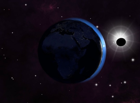
Post Processing
Of course, we could continue enhancing our experiment indefinitely, but for the purpose of this tutorial, we are going to do just one more thing to it: Pimp up the graphics with a bit of post processing. That is, we won’t be working on the scene itself anymore, but will be adding a few rendering effects on top of our current result. We will add a bloom effect as a GPU Filter3D and a lens flare effect via the regular Flash display API using Bitmap objects. Let’s see how it will look like.
Listing 9. Postprocessing with bloom and lens flare effects. Full source code.
Ain’t it cool? Let’s have a look at how each of the effects are accomplished.
Bloom Effect
Away3D offers an awesome, extensible post processing kit via the filters package. These effects can be considered to be shaders, but instead of acting on independent materials and regular 3D geometry, work on the final output of the scene’s rendering and drawing the result on a quad that perfectly fits the screen. This gives us the possibility of using the GPU’s vast processing power for global scene rendering effects. In this case, we are using a bloom filter. You can read about it here. Basically, a bloom filter emulates how lenses experience film over exposure by very bright light sources. On our case, we use it when looking directly at the sun. To set up filters in Away3D we simply initialize the objects and set them as the view’s filters3d array. You can chain multiple filters in this way.
Then, at runtime, we evaluate the strength ( exposure parameter ) of the filter by calculating ‘how much in front of the sun’ the viewer is. This is done in the updateBloom() method, mainly by projecting the camera position onto the X axis ( along which the sun lays ). This value is used as well to slightly scale up the sun Sprite3D.
Lens Flare Effect
This is a classical 2D, regular Flash display API, lens flare effect. We simply load a few bitmaps, place them on top of our view and align them to produce the desired effect. What’s interesting is how we evaluate the position and visibility of the flares in the updateFlares() method. The most important part of this method is the usage of view.project( vector:Vector3D ). This method takes a scene position in 3D space and transforms it to 2D screen space. We evaluate the visibility of our flares by first determining if the sun is in the screen and by also checking if the sun is occluded by the Earth. Notice that we are not considering occlusion for the Moon, but we could! We’ve also embedded the mini class FlareObject just to make the manipulation of our flares a bit easier for us.
That looks good doesn’t it?
Conclusion
This concludes our little Planet Earth simulation. We started with a very basic scene in terms of geometry and shading and step by step enhanced the way it looked. First, we used a sky box and billboards to enrich the scene, and then we meticulously focused on enhancing the materials of the Earth. This even got us into coding a bit of AGAL. With all this, you should now be a bit more familiar with Away3D’s powerful and flexible material system, which allows us to produce some pretty stunning visual effects. Surely, you could enhance our experiment greatly, since we’ve kept things as simple as possible here. You could move on though, since you have the full power of the GPU to accomplish whatever effect is in your creative mind, and Away3D makes it very easy for us to make these ideas happen.